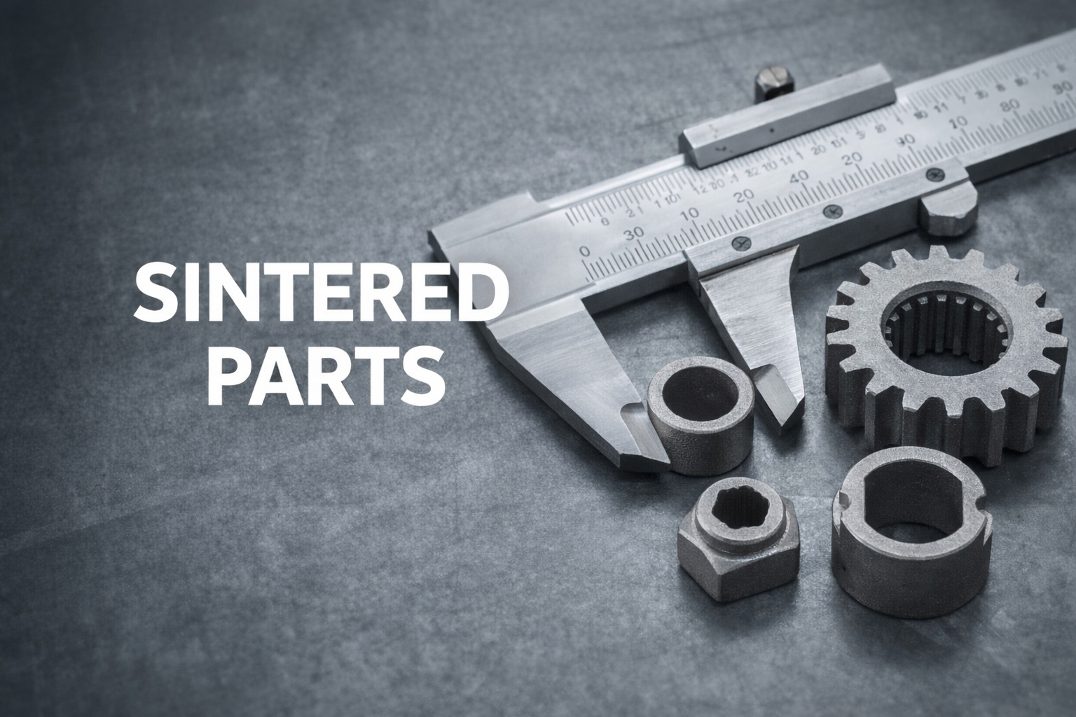
Sintered parts are widely used in high-volume manufacturing where cost efficiency, dimensional stability, and repeatability are more critical than extreme geometric complexity. In industries such as automotive, industrial equipment, consumer hardware, and power tools, sintered metal parts remain a practical and scalable solution.
However, sintering is not a universal answer. Understanding the material limits, density range, achievable tolerances, and design constraints is essential before selecting this process—especially when comparing sintered parts with Metal Injection Molding (MIM) or CNC machining.
This article provides a practical, engineering-focused overview of parts, with real parameters, comparison tables, and decision guidance.

Engineering Quick Reference – Sintered Parts
| Parameter | Typical Range |
|---|---|
| Relative Density | 85–95% of wrought material |
| Porosity | 5–15% |
| As-sintered Tolerance | ±0.05–0.10 mm |
| Sized Tolerance | ±0.01–0.02 mm |
| Recommended Volume | 10,000 – 1,000,000 pcs |
| Suitable Geometry | Simple, axial parts |
| Alternative Process | Metal Injection Molding (MIM) |
1. What are Sintered Parts?
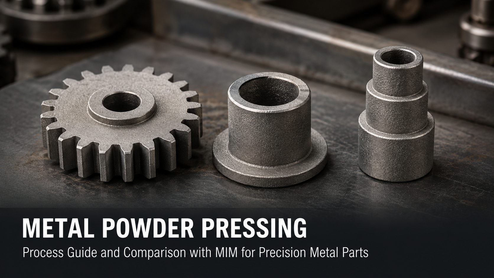
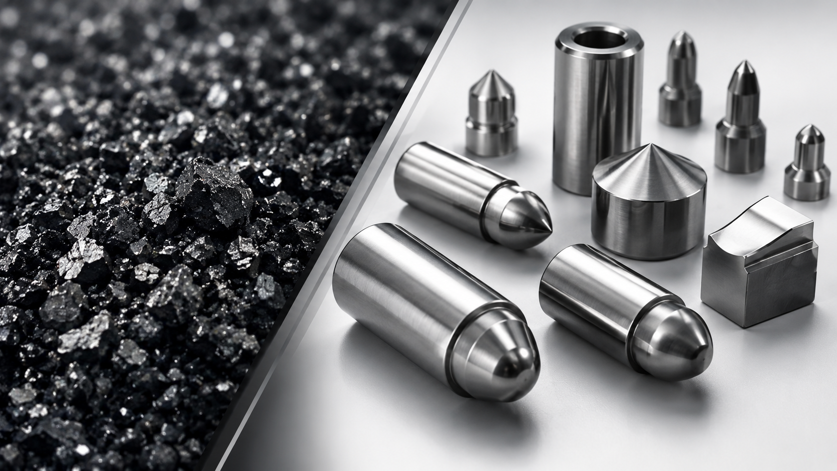
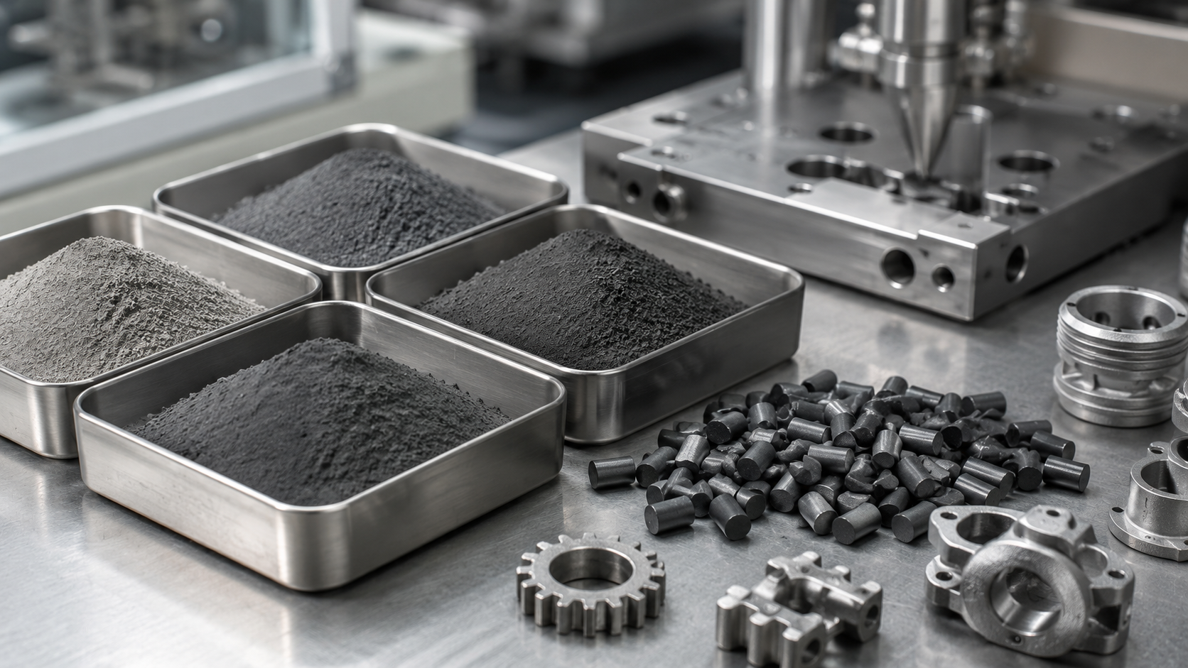
Sintered parts are manufactured using powder metallurgy (PM) processes. Metal powders are compacted in a rigid die under high pressure and then heated to a temperature below the melting point of the base metal. During sintering, particles bond through solid-state diffusion, forming a mechanically stable component.
Basic Sintering Process Flow
| Step | Description |
|---|---|
| Powder preparation | Metal or alloy powders with controlled particle size |
| Compaction | Uniaxial pressing in a rigid die |
| Sintering | High-temperature bonding below melting point |
| Secondary operations | Sizing, impregnation, machining (if required) |
Unlike MIM, sintered parts do not involve molten feedstock flow, which significantly limits achievable geometry but improves cost efficiency for simpler shapes.

2. Common Materials Used for Sintered Parts
Material selection directly affects density, strength, corrosion resistance, and cost. The table below summarizes commonly used materials in industrial sintered parts.
Typical Materials and Density Range
| Material | Typical Density (g/cm³) | Key Characteristics |
|---|---|---|
| Iron (Fe) | 6.6 – 7.2 | Lowest cost, structural parts |
| Fe-Cu-C alloys | 6.8 – 7.3 | Improved strength, automotive components |
| Stainless steel (304 / 316) | 6.8 – 7.4 | Corrosion resistance |
| Bronze | 6.5 – 7.5 | Self-lubricating, bearings |
| Copper | 7.2 – 8.2 | Electrical and thermal conductivity |
Engineering reality:
Standard sintered parts are not fully dense. Density typically ranges from 85% to 95% of wrought material, which directly impacts mechanical performance.

3. Key Engineering Properties of Sintered Parts
3.1 Density and Porosity
Porosity is both a limitation and an advantage, depending on application.
| Relative Density | Porosity Level | Typical Applications |
|---|---|---|
| 85–88% | High | Oil-impregnated bearings |
| 88–92% | Medium | Structural brackets |
| 92–95% | Low | Gears, load-bearing components |
Porosity enables lubrication retention but reduces fatigue strength and impact resistance.
3.2 Mechanical Strength
Mechanical properties vary significantly based on material system and density level.
| Material Type | Tensile Strength (MPa) |
|---|---|
| Iron-based sintered parts | 250 – 600 |
| Stainless steel sintered parts | 400 – 700 |
Heat treatment and alloying can improve performance, but fully dense behavior cannot be assumed.
3.3 Dimensional Tolerances
Dimensional accuracy is influenced by pressing direction, tool wear, and density gradients.
| Feature | Typical Tolerance |
|---|---|
| Pressing direction | ±0.02 – 0.05 mm |
| Transverse direction | ±0.05 – 0.10 mm |
| After sizing operation | ±0.01 – 0.02 mm |
Tight tolerances usually require secondary sizing or light machining, which increases cost.

4. Design Constraints for Sintered Parts
Design for sintering is critical. Ignoring process constraints often leads to tooling issues or post-machining.
Practical Design Guidelines
| Design Element | Recommendation |
|---|---|
| Minimum wall thickness | ≥ 1.0 mm |
| Corner radius | ≥ 0.5 mm |
| Hole orientation | Parallel to pressing direction |
| Wall thickness variation | Keep uniform |
Key limitation:
Side holes, undercuts, and complex internal features are difficult or impossible without secondary operations.
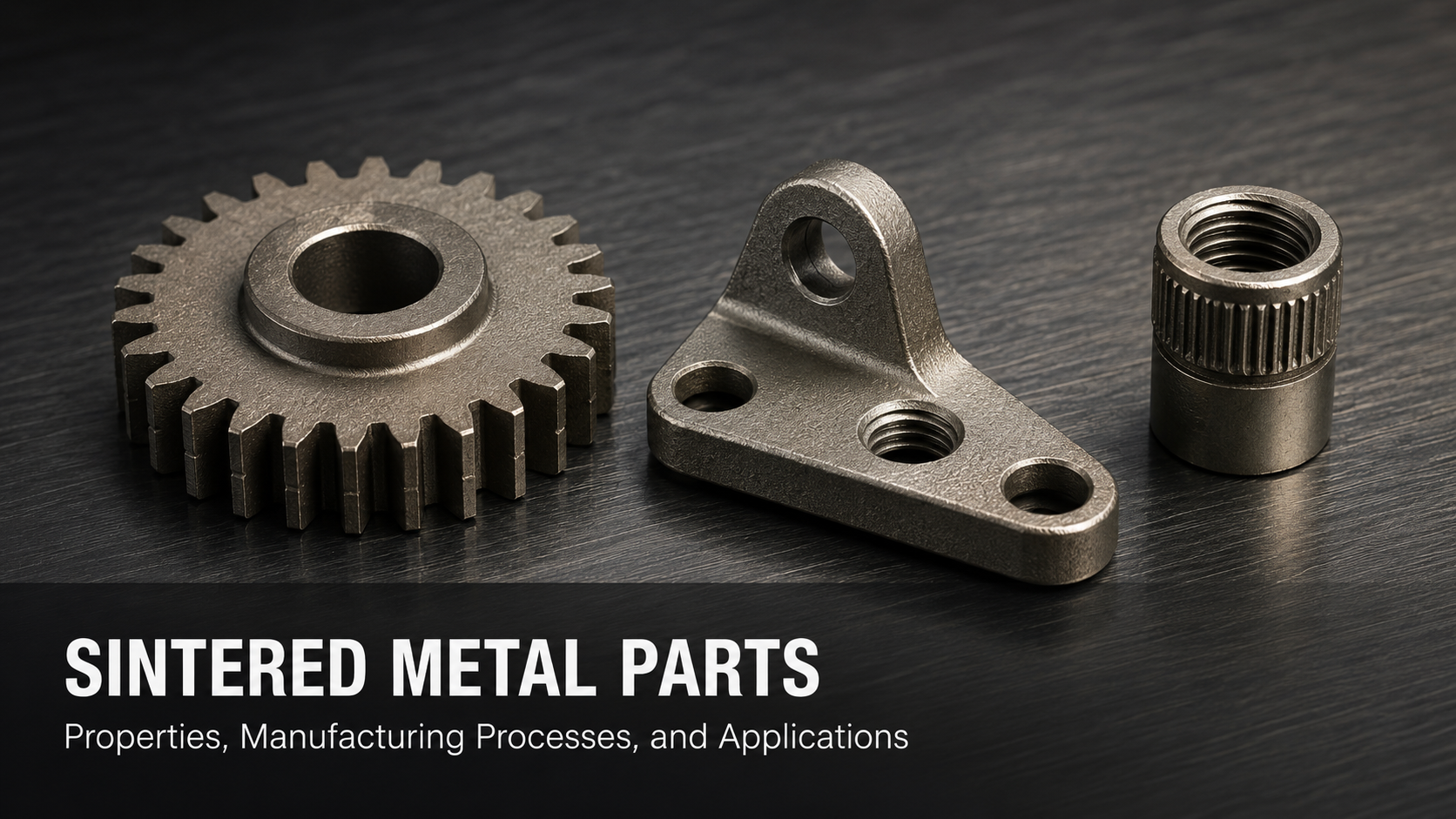
5. Typical Applications of Sintered Parts
Sintered parts are best suited for high-volume, mechanically simple components.
| Application | Why Sintering Works |
|---|---|
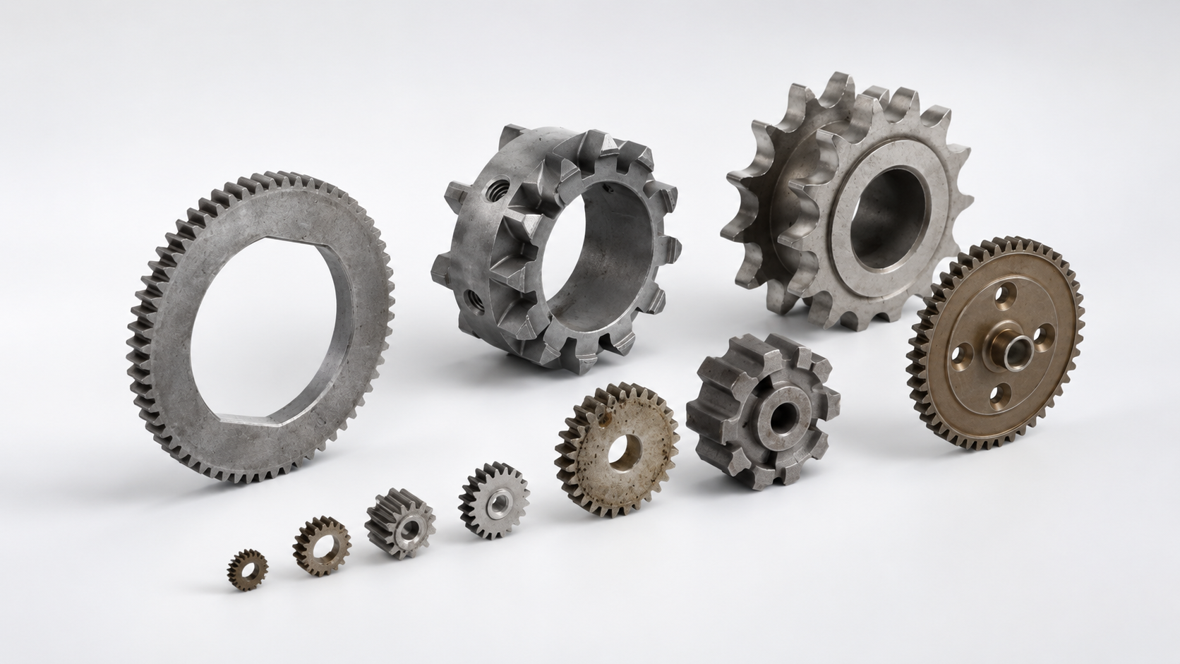
| Gears and sprockets | Near-net shape, low cost |
| Bushings and bearings | Controlled porosity |
| Structural brackets | Dimensional stability |
| Lock components | High-volume repeatability |
| Power tool parts | Cost-driven designs |
6. Sintered Parts vs MIM vs CNC Machining
For design engineers and sourcing teams, process selection often comes down to geometry, volume, and performance.
Manufacturing Process Comparison
| Factor | Sintered Parts | MIM | CNC Machining |
|---|---|---|---|
| Tooling cost | Medium | High | None |
| Unit cost (high volume) | Lowest | Medium | High |
| Density | 85–95% | 96–99% | ~100% |
| Geometric complexity | Low–Medium | High | Medium |
| Best production volume | 10k – 1M+ | 50k – 1M | Low volume |
7. When Sintered Parts Are NOT the Right Choice
Sintered parts are not recommended for the following conditions:
-
Ultra-thin walls (< 0.8 mm)
-
Complex internal channels
-
High-impact or cyclic fatigue loads
-
Medical or aerospace components requiring near-full density
-
Tight multi-directional tolerances without secondary machining
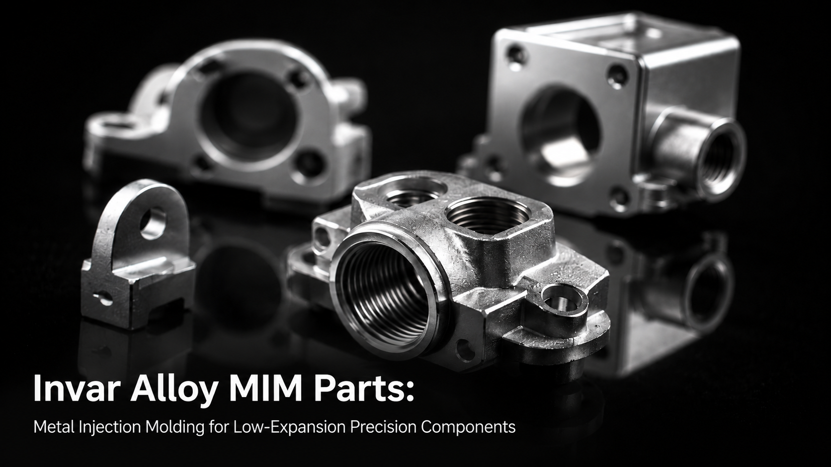
In these cases, Metal Injection Molding (MIM) often provides a more reliable solution.
8. Why MIM Is Often Chosen Over Traditional Sintering
MIM combines powder metallurgy with plastic injection molding, enabling:
-
Near-full density (up to 99%)
-
Complex 3D geometries
-
Fine surface finish
-
Tighter overall tolerances
Practical Decision Rule
| Requirement | Recommended Process |
|---|---|
| Simple geometry, cost-driven | Sintered parts |
| Complex geometry, high strength | MIM |
| Low volume, flexible changes | CNC machining |
9. Engineering Decision Checklist
Before finalizing sintered parts for your project, evaluate:
-
Required mechanical strength
-
Acceptable porosity level
-
Geometry complexity
-
Tolerance requirements
-
Annual production volume
Early process selection can significantly reduce redesign cycles and total cost.
10. Conclusion
Sintered parts remain a cost-effective and scalable solution for many industrial applications. However, their limitations in density and geometry must be clearly understood during the design phase.
For components requiring higher strength, tighter tolerances, or complex geometry, Metal Injection Molding offers a more suitable manufacturing path.
Selecting the right process at the beginning is not about choosing the cheapest method—but choosing the one that meets functional requirements with minimal downstream risk.
Frequently Asked Questions(FAQ)
1. What density can sintered parts realistically achieve?
Most sintered parts achieve 85–95% of wrought material density, depending on material system and compaction pressure.
2. How does porosity affect mechanical strength?
Higher porosity reduces fatigue and impact resistance but can enable oil impregnation in bearing applications.
3. Can sintered parts be machined after sintering?
Yes. Secondary machining or sizing is often used to achieve tighter tolerances or functional features.
4. What tolerances are realistic without secondary operations?
Typical as-sintered tolerances range from ±0.05 to ±0.10 mm.
5. When should MIM be selected instead?
MIM is preferred when complex geometry, thin walls, or near-full density is required.
Share:
Powder Metal Gears and the Atomization Process
The Ultimate Guide to Powder Metal Manufacturing: Process, Advantages, and Applications