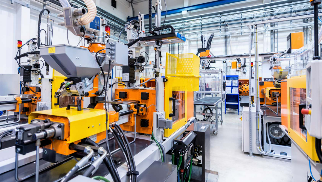
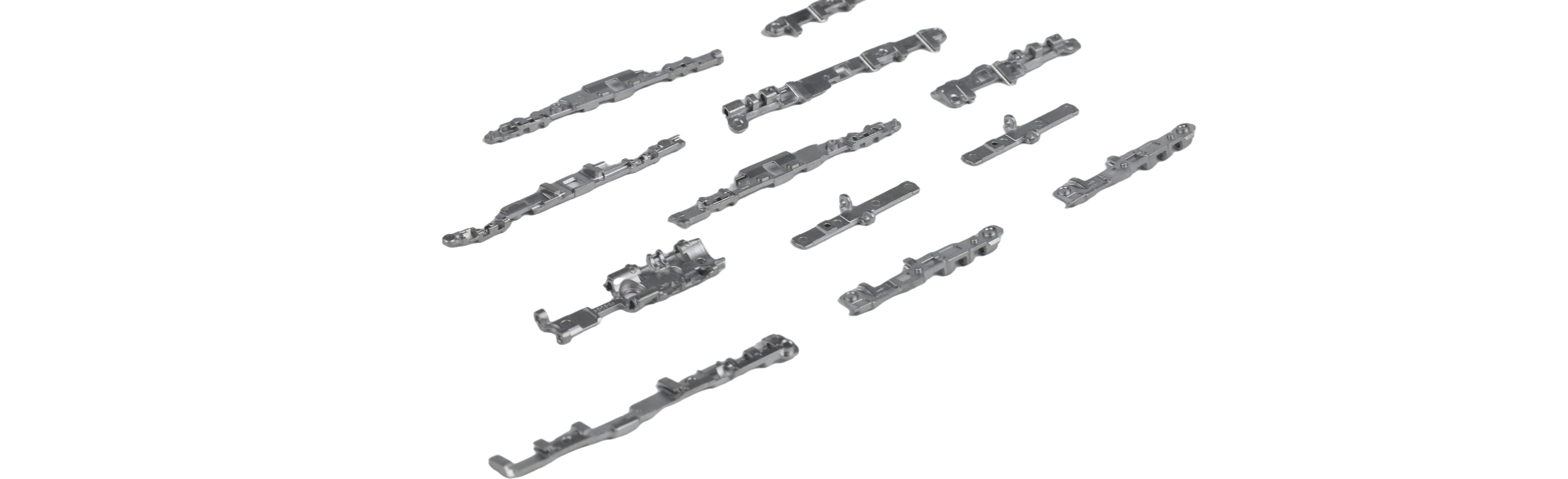
A major factor to consider when designing a part for manufacture with MIM is tooling design. MIM tooling requires very specific design features; these include parting lines, gates, ejector pin marks, and cam actions.
Parting Lines: Every MIM part will have a witness line from where the two halves of the mold come together to form the cavity. However, creative design can help to hide the parting line. Stepping the parting line down the edge of a feature will make the parting line less apparent.
Gating: The gate is where the MIM feedstock is injected into the cavity. There are four most common gate types: tab, tunnel, jump and drop. Each gate type leaves a small vestige, so placement is complicated. You also want to gate into an area of the part with the largest cross section, so you fill the part from thick to thin. On cylindrical parts, filling as close to the center axis as possible will help prevent sintering distortion.
Ejector Pins: Ejector pins serve to remove the part from the tool cavity. However, ejector pins leave witness marks on the part. Consider designing the part in a way to place these marks in an area that is unseen on the part when it is assembled.
Cam Actions: Cam actions allow undercuts to be formed in the part, without the need for secondary operations. When designing a part with undercuts, keep in mind what direction a cam will have to move in to form the undercut. Design becomes more complicated when multiple cam actions are needed, because each one takes up a lot of space within the tool itself.


Share:
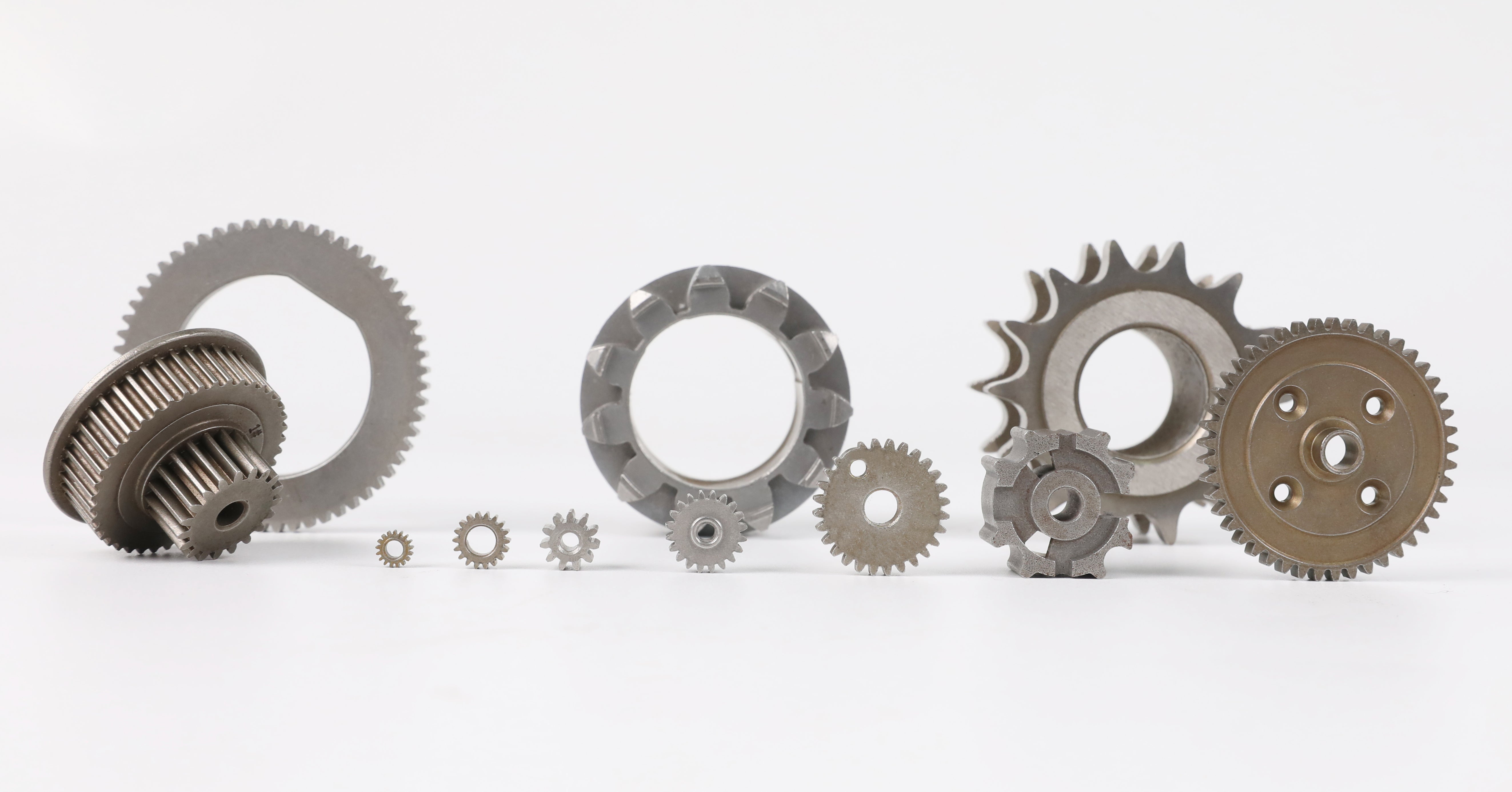
Unique Aspects of MIM
Abrasive Vs Pure Waterjet Cutting, Which Is Better