Спеченные детали широко используются в крупносерийном производстве, где экономическая эффективность, стабильность размеров и повторяемость важнее, чем чрезвычайная геометрическая сложность. В таких отраслях, как автомобилестроение, промышленное оборудование, потребительская электроника и электроинструменты, спеченные металлические детали остаются практичным и масштабируемым решением.
Однако спекание не является универсальным ответом. Понимание пределов материала, диапазона плотности, достижимых допусков и конструктивных ограничений является важным условием до выбора этого процесса, особенно при сравнении спеченных деталей с литьем металлов под давлением (MIM) или обработкой на станках с ЧПУ.
Эта статья содержит практический обзор деталей, ориентированный на инженеров, с реальными параметрами, сравнительными таблицами и рекомендациями по принятию решений.

Краткий справочник инженера — спеченные детали
| Параметр | Типичный диапазон |
|---|---|
| Относительная плотность | 85–95% от плотности деформированного материала |
| Пористость | 5–15% |
| Допуск после спекания | ±0,05–0,10 мм |
| Допуск после калибровки | ±0,01–0,02 мм |
| Рекомендуемый объем | 10 000 – 1 000 000 шт. |
| Подходящая геометрия | Простые, осесимметричные детали |
| Альтернативный процесс | Литье металлов под давлением (MIM) |
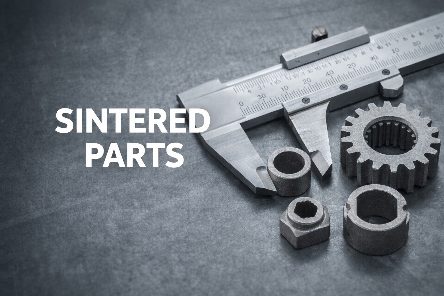
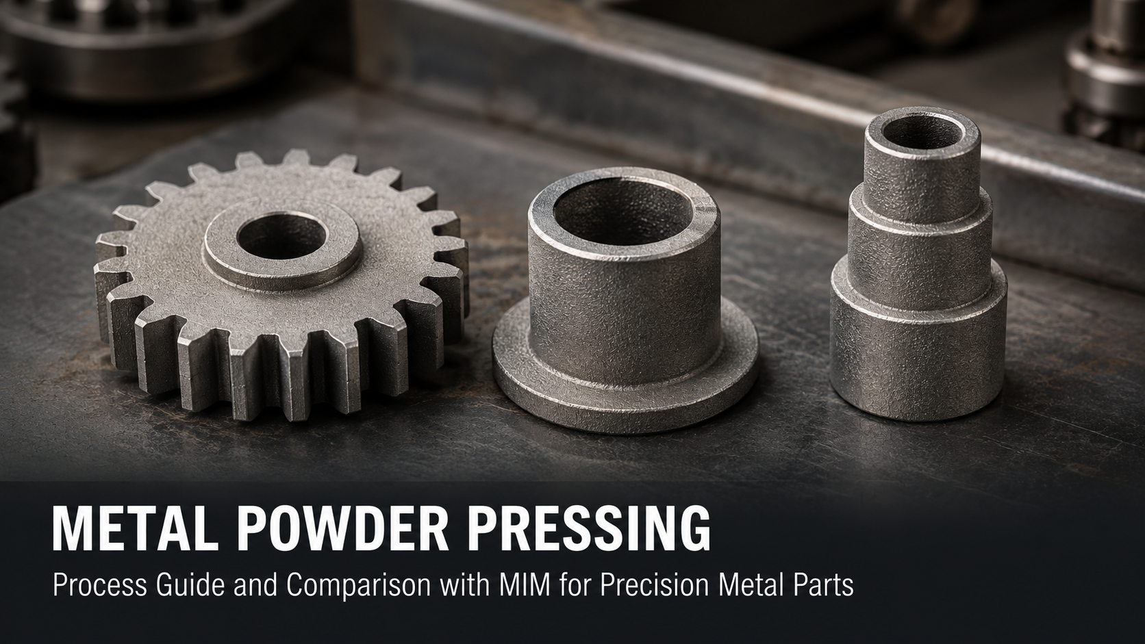
1. Что такое спеченные детали?
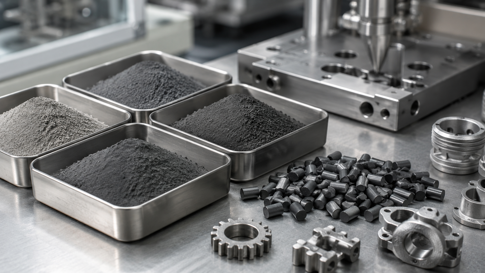
Спеченные детали изготавливаются с использованием процессов порошковой металлургии (ПМ). Металлические порошки уплотняются в жесткой матрице под высоким давлением, а затем нагреваются до температуры ниже точки плавления основного металла. Во время спекания частицы связываются посредством твердофазной диффузии, образуя механически стабильный компонент.
Базовая схема процесса спекания
| Этап | Описание |
|---|---|
| Подготовка порошка | Металлические или сплавные порошки с контролируемым размером частиц |
| Компактирование | Одноосное прессование в жесткой матрице |
| Спекание | Высокотемпературное связывание ниже точки плавления |
| Вторичные операции | Калибровка, пропитка, механическая обработка (при необходимости) |
В отличие от MIM, спеченные детали не предполагают течения расплавленного сырья, что значительно ограничивает достижимую геометрию, но повышает экономическую эффективность для более простых форм.

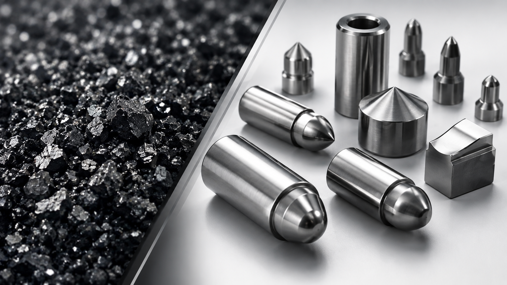
2. Распространенные материалы, используемые для спеченных деталей
Выбор материала напрямую влияет на плотность, прочность, коррозионную стойкость и стоимость. В таблице ниже приведены обычно используемые материалы для промышленных спеченных деталей.
Типичные материалы и диапазон плотности
| Материал | Типичная плотность (г/см³) | Основные характеристики |
|---|---|---|
| Железо (Fe) | 6,6 – 7,2 | Низкая стоимость, конструкционные детали |
| Сплавы Fe-Cu-C | 6,8 – 7,3 | Повышенная прочность, автомобильные компоненты |
| Нержавеющая сталь (304 / 316) | 6,8 – 7,4 | Коррозионная стойкость |
| Бронза | 6,5 – 7,5 | Самосмазывающиеся, подшипники |
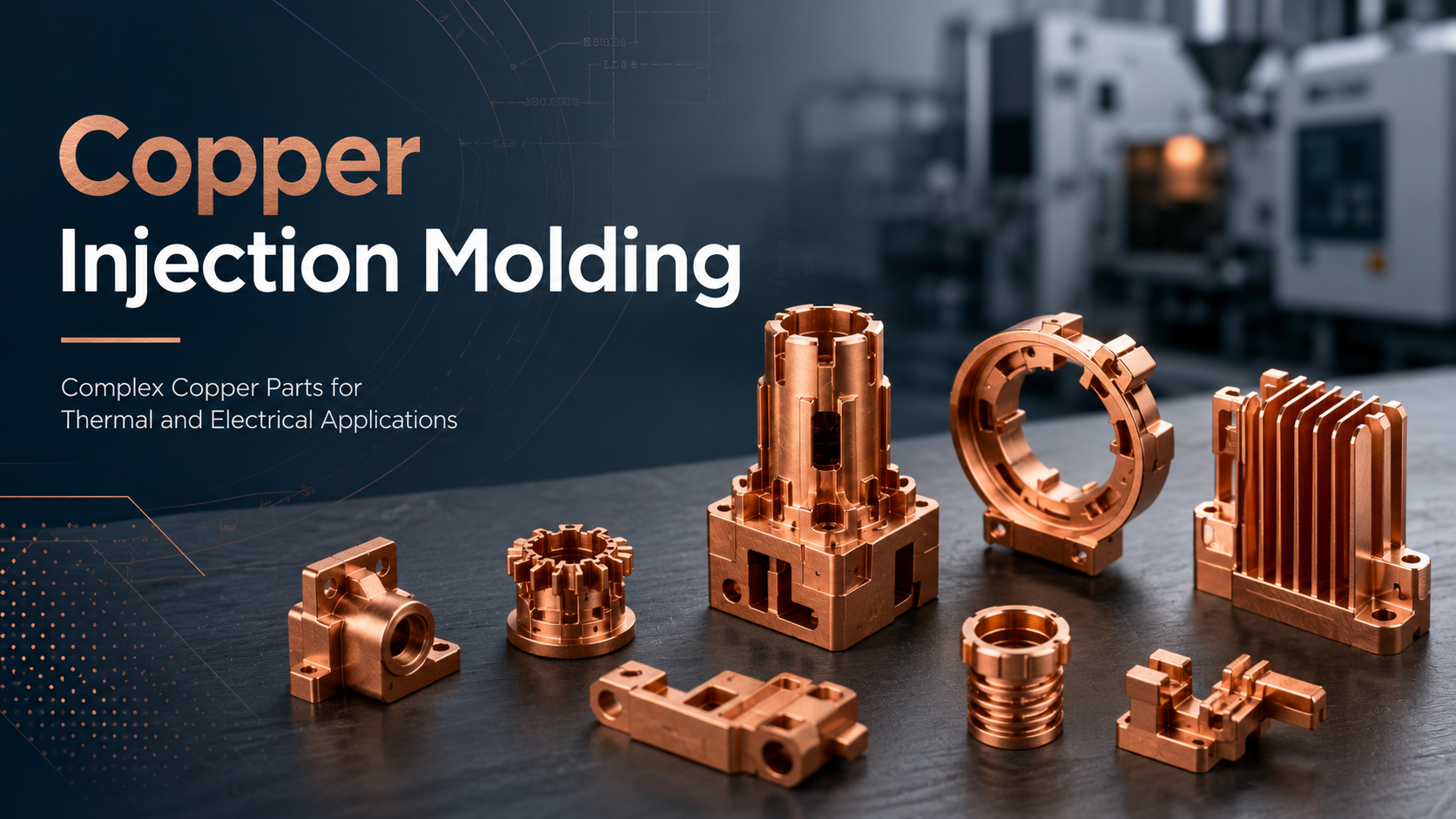
| Медь | 7,2 – 8,2 | Электрическая и тепловая проводимость |
Инженерная реальность:
Стандартные спеченные детали не являются полностью плотными. Плотность обычно составляет от 85% до 95% от плотности деформированного материала, что напрямую влияет на механические характеристики.

3. Основные инженерные свойства спеченных деталей
3.1 Плотность и пористость
Пористость является как ограничением, так и преимуществом, в зависимости от применения.
| Относительная плотность | Уровень пористости | Типичные применения |
|---|---|---|
| 85–88% | Высокий | Маслопропитанные подшипники |
| 88–92% | Средний | Конструкционные кронштейны |
| 92–95% | Низкий | Шестерни, несущие компоненты |
Пористость обеспечивает удержание смазки, но снижает усталостную прочность и ударную вязкость.
3.2 Механическая прочность
Механические свойства значительно варьируются в зависимости от системы материала и уровня плотности.
| Тип материала | Предел прочности на разрыв (МПа) |
|---|---|
| Спеченные детали на основе железа | 250 – 600 |
| Спеченные детали из нержавеющей стали | 400 – 700 |
Термическая обработка и легирование могут улучшить характеристики, но полная плотность не может быть гарантирована.
3.3 Допуски на размеры
Точность размеров зависит от направления прессования, износа инструмента и градиентов плотности.
| Характеристика | Типичный допуск |
|---|---|
| Направление прессования | ±0,02 – 0,05 мм |
| Поперечное направление | ±0,05 – 0,10 мм |
| После операции калибровки | ±0,01 – 0,02 мм |
Для жестких допусков обычно требуется вторичная калибровка или легкая механическая обработка, что увеличивает стоимость.

4. Конструктивные ограничения для спеченных деталей
Проектирование для спекания имеет решающее значение. Игнорирование технологических ограничений часто приводит к проблемам с оснасткой или последующей механической обработке.
Практические рекомендации по проектированию
| Элемент дизайна | Рекомендация |
|---|---|
| Минимальная толщина стенки | ≥ 1,0 мм |
| Радиус угла | ≥ 0,5 мм |
| Ориентация отверстия | Параллельно направлению прессования |
| Изменение толщины стенки | Соблюдайте равномерность |
Основное ограничение:
Боковые отверстия, поднутрения и сложные внутренние элементы трудно или невозможно изготовить без вторичных операций.
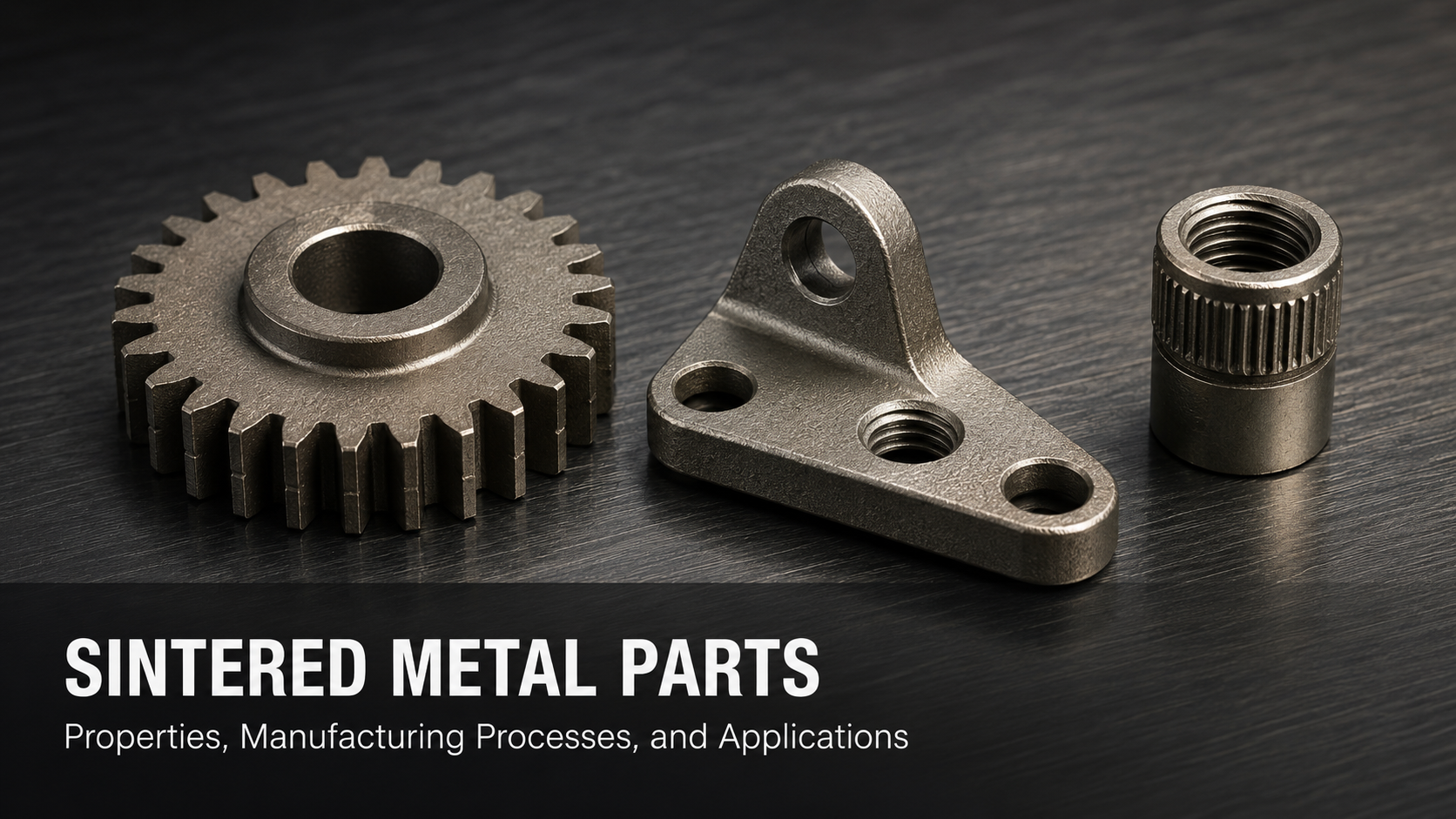
5. Типичные области применения спеченных деталей
Спеченные детали лучше всего подходят для крупносерийных, механически простых компонентов.
| Применение | Почему спекание эффективно |
|---|---|
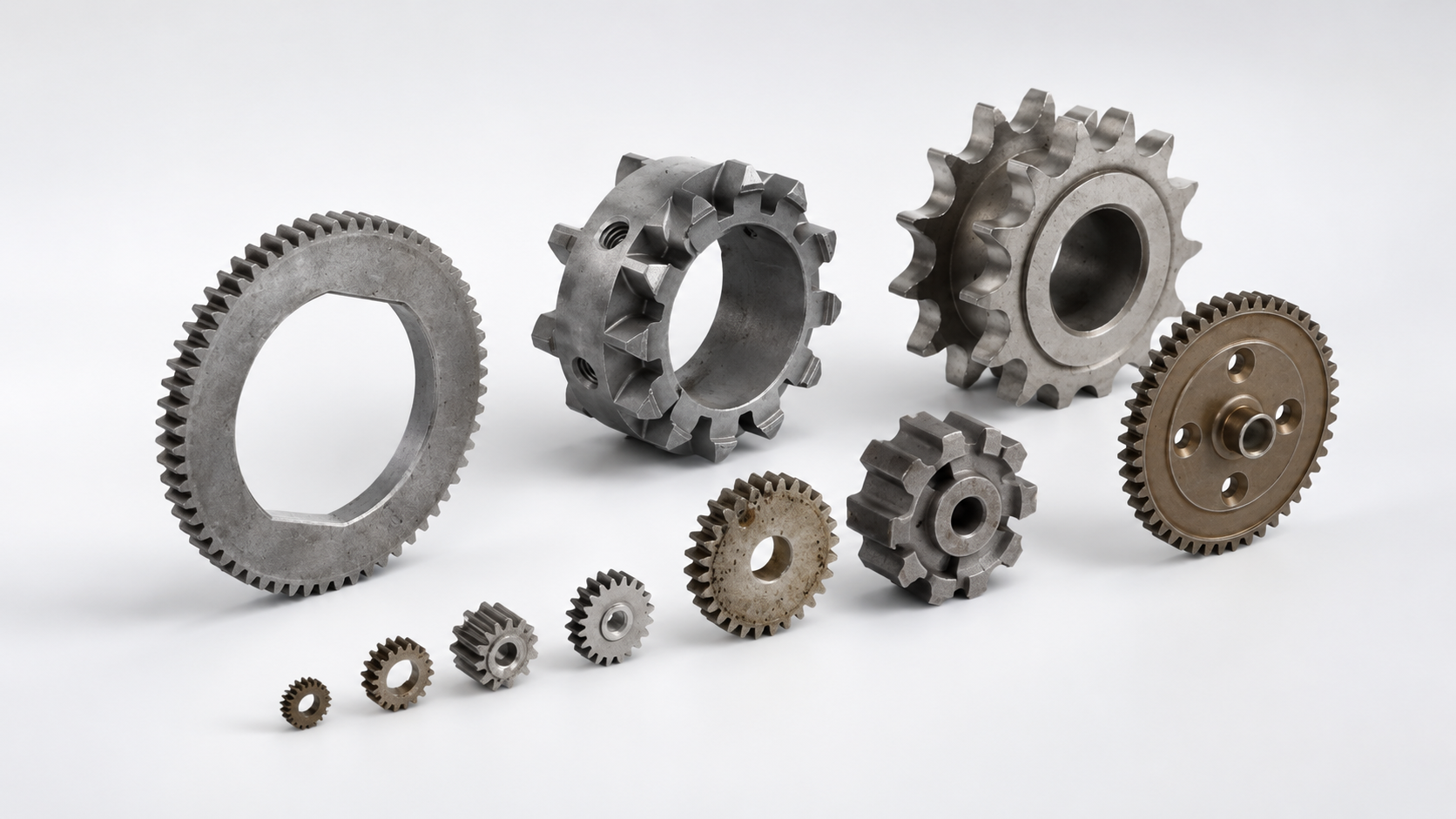
| Шестерни и звездочки | Приближенная к окончательной форма, низкая стоимость |
| Втулки и подшипники | Контролируемая пористость |
| Конструкционные кронштейны | Стабильность размеров |
| Детали замков | Повторяемость при больших объемах |
| Детали электроинструментов | Конструкции, ориентированные на стоимость |
6. Спеченные детали против MIM против механической обработки на станках с ЧПУ
Для инженеров-конструкторов и групп по закупкам выбор процесса часто сводится к геометрии, объему и производительности.
Сравнение производственных процессов
| Фактор | Спеченные детали | MIM | Механическая обработка на станках с ЧПУ |
|---|---|---|---|
| Стоимость оснастки | Средняя | Высокая | Нет |
| Себестоимость единицы (большой объем) | Самая низкая | Средняя | Высокая |
| Плотность | 85–95% | 96–99% | ~100% |
| Геометрическая сложность | Низкая–средняя | Высокая | Средняя |
| Наилучший объем производства | 10 тыс. – 1 млн+ | 50 тыс. – 1 млн | Малый объем |
7. Когда спеченные детали НЕ являются правильным выбором
Спеченные детали не рекомендуются для следующих условий:
-
Ультратонкие стенки (< 0,8 мм)
-
Сложные внутренние каналы
-
Высокие ударные или циклические усталостные нагрузки
-
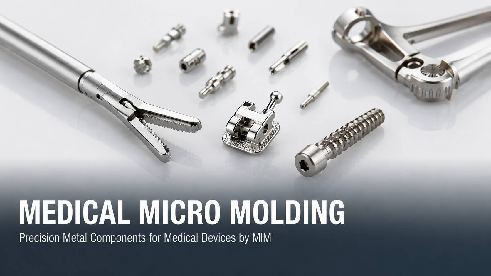
Медицинские или аэрокосмические компоненты, требующие почти полной плотности
-
Жесткие разнонаправленные допуски без вторичной механической обработки
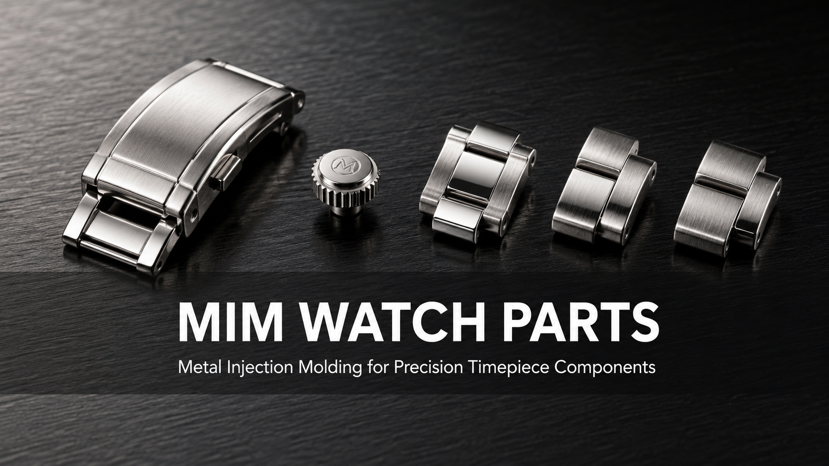
В таких случаях литье металлов под давлением (MIM) часто является более надежным решением.
8. Почему MIM часто выбирают вместо традиционного спекания
MIM сочетает порошковую металлургию с литьем пластмасс под давлением, что позволяет:
-
Почти полная плотность (до 99%)
-
Сложные 3D-геометрии
-
Отличная чистота поверхности
-
Более жесткие общие допуски
Практическое правило принятия решений
| Требование | Рекомендуемый процесс |
|---|---|
| Простая геометрия, низкая стоимость | Спеченные детали |
| Сложная геометрия, высокая прочность | MIM |
| Малый объем, гибкие изменения | Механическая обработка на станках с ЧПУ |
9. Контрольный список для принятия инженерных решений
Прежде чем окончательно выбрать спеченные детали для вашего проекта, оцените:
-
Необходимая механическая прочность
-
Допустимый уровень пористости
-
Сложность геометрии
-
Требования к допускам
-
Годовой объем производства
Ранний выбор процесса может значительно сократить циклы перепроектирования и общую стоимость.
10. Заключение
Спеченные детали остаются экономически эффективным и масштабируемым решением для многих промышленных применений. Однако их ограничения по плотности и геометрии должны быть четко поняты на этапе проектирования.
Для компонентов, требующих более высокой прочности, более жестких допусков или сложной геометрии, литье металлов под давлением предлагает более подходящий производственный путь.
Выбор правильного процесса в самом начале заключается не в выборе самого дешевого метода, а в выборе того, который соответствует функциональным требованиям с минимальными рисками в дальнейшем.
Часто задаваемые вопросы (FAQ)
1. Какой плотности могут реально достичь спеченные детали?
Большинство спеченных деталей достигают 85–95% плотности деформированного материала, в зависимости от системы материала и давления уплотнения.
2. Как пористость влияет на механическую прочность?
Высокая пористость снижает усталостную и ударную вязкость, но может обеспечить пропитку маслом в подшипниковых узлах.
3. Можно ли спеченные детали обрабатывать после спекания?
Да. Вторичная механическая обработка или калибровка часто используется для достижения более жестких допусков или функциональных особенностей.
4. Какие допуски являются реалистичными без вторичных операций?
Типичные допуски после спекания составляют от ±0,05 до ±0,10 мм.
5. Когда следует выбирать MIM вместо спекания?
MIM предпочтительнее, когда требуется сложная геометрия, тонкие стенки или почти полная плотность.
Делиться:
Шестерни из порошкового металла и процесс распыления
Полное руководство по производству порошковых металлов: процесс, преимущества и применение